Photogrammetry in OrtogOnBlender XP: The Story of an (R)Evolution
Attention
This material is licensed under the following Creative Commons license: Attribution 4.0 International (CC BY 4.0).
Abstract
This study presents the historical evolution and technical advancements of photogrammetry integrated into OrtogOnBlender XP, a free and open-source Blender add-on designed for digital surgical planning. Originating in 2012 with forensic reconstructions and pioneering applications — such as the world’s first 3D-printed tortoise shell prosthesis, recognized by Guinness World Records in 2022 — the tool has evolved to its current version incorporating an optimized OpenMVG+OpenMVS pipeline. The main innovation is the introduction of fully automatic 1:1 real-world scaling and alignment through ArUco marker detection, requiring only a single planar marker containing at least four elements for reliable accuracy — using photographs taken with ordinary mid-range smartphones. Rigorous comparative tests employing a digital skull of known dimensions and real photographic sequences demonstrated that the new “Ultra!” configuration with CUDA acceleration achieves structural accuracy and surface detail quality equal to or surpassing leading proprietary software (RealityCapture, Metashape, and Zephyr). By overcoming the historical limitation of lacking automatic metric scaling in open-source solutions, OrtogOnBlender XP establishes a complete, accessible, and clinically validated workflow for 3D facial digitization, with applications in orthognathic surgery, rhinoplasty, maxillofacial oncological prostheses, veterinary medicine, and general 3D digitization.
Keywords: SfM, Structure from Motion, Photogrammetry, OrtogOnBlender XP, Open Source Software.
Introduction
The OrtogOnBlender, an add-on for digital surgical planning, was created in 2017 and, among its first features, stood out the 3D digitization from photographs, also known generically as photogrammetry and, technically, as Structure from Motion (SfM). However, the development of the tool dates back to 2012, when the authors began a technological collaboration that culminated in the interface presented here.
The first practical outcome of this partnership was the facial reconstruction of the Taung Child, performed from a skull digitized in 3D using photogrammetry [Bezzi_et_al_2013_b]. This work gave rise to a temporary exhibition in Padua, later converted into a permanent exhibition at the Museo della Natura e dell’Uomo [Carrara_et_al_2023_b]. All 24 fossils used were digitized with the same technique.
There were, however, concerns regarding the accuracy of the digital models compared to the real skulls. To address these, a comparative study was conducted using six skulls digitized with a structured-light scanner (gold standard) and their counterparts obtained from photographs [Dias_et_al_2013_b]. The results revealed submillimetric structural differences. At that time, the tool employed was PPT-GUI, which generated models with vertex color rather than image-based texturing, yet the results were so promising that the poster won first place at a Forensic Anthropology event held at the University of São Paulo (USP) in 2013.
Gradually, professionals from other fields began adopting the technique: initially for manufacturing prostheses and ortheses [Munhoz_et_al_2016_b], later for human surgical planning, and subsequently in veterinary medicine [Moulon_et_al_2017_b] and other applications requiring such tools.
One project that used PPT-GUI (developed by two of the authors) [Moulon_and_Bezzi_2011_b] and gained worldwide recognition was the prosthesis for the turtle Fred — the world’s first — created in 2015 [Rabello_et_al_2016_b], pigmented, went internationally viral in 2016, and was officially recognized by the Guinness World Records in the 2022 edition.
As the technique evolved, so did the code. In 2013, OpenMVG was created, making camera calibration faster and more accurate [Moulon_et_al_2017_b]. Together with OpenMVS, it enabled the accessible creation of high-resolution, impeccably textured three-dimensional models from photographs — something that, although possible with PPT-GUI, required additional steps in external applications.
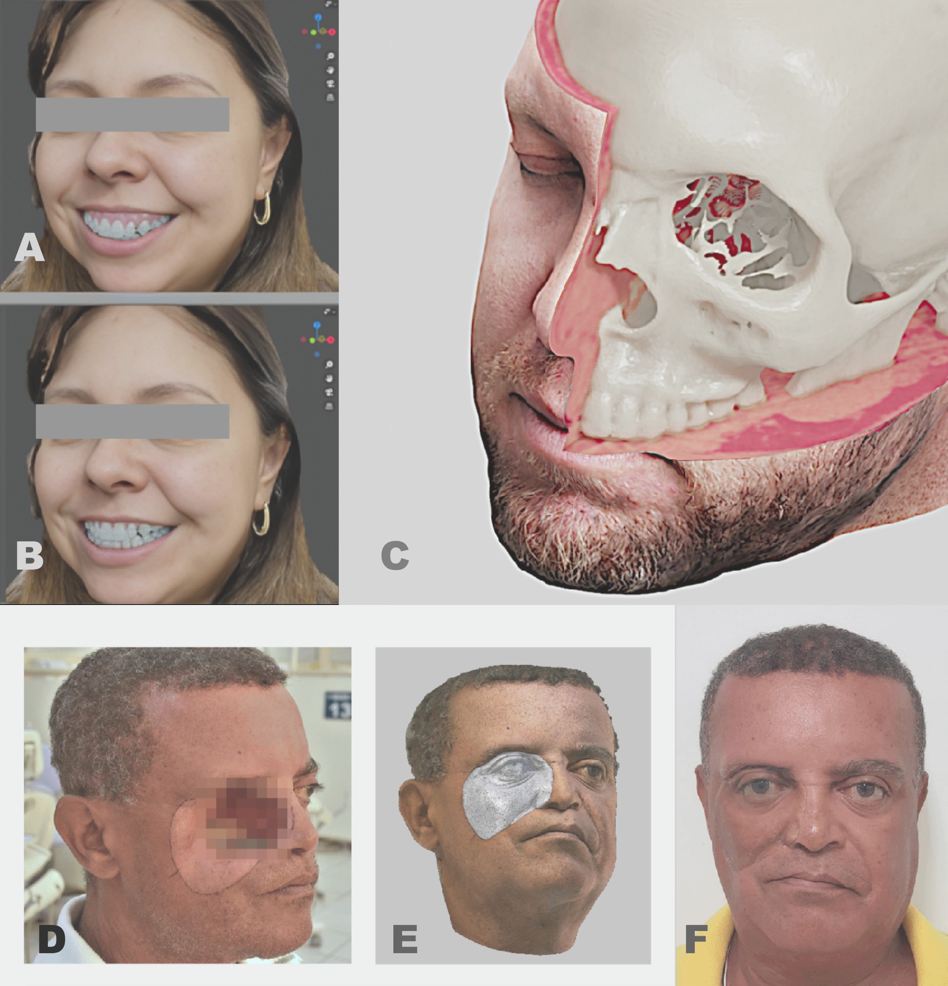
Fig. 9 A) Digital pre-surgical; B) Digital post-surgical; C) Composite of photogrammetry + computed tomography (voxel data) + computed tomography reconstructed as 3D mesh (skull); D) Patient with exposure of the orbital region (photo); E) 3D digitization by photogrammetry with mirroring of the healthy side for prosthesis design, using surface details from the normal texture map; F) Directly 3D-printed prosthesis positioned at the defect site. All procedures were performed in OrtogOnBlender using OpenMVG+OpenMVS.
In 2017, OrtogOnBlender was released and incorporated the OpenMVG+OpenMVS duo into its suite, enabling high-resolution facial digitization. This made possible the assessment of bony deformity corrections in relation to the face (Fig. 9), the fabrication of facial prostheses for oncology patients [Salazar-Gamarra_et_al_2022_b], digital rhinoplasty [Sobral_et_al_2021_b], urological data documentation [Nacimento_et_al_2023_b], and many other applications.
One of the main problems with photogrammetry — and a frequent source of complaints, especially among novice users — was that the mesh was generated without real-world scale, requiring manual resizing prone to user error. In 2022, this limitation was overcome by integrating ArUco markers: simply placing the marker near the face (or any object) allowed the system to automatically scale and align the model coherently with the real world [Moraes_et_al_2022_b].
That same year, an absolute accuracy test was conducted by directly photogrammetrizing a virtual scene (with known dimensions) and comparing the results against both open-source and proprietary photogrammetry tools. Twenty-nine meshes were generated using six different software packages (three open-source and three proprietary). The OpenMVG+OpenMVS combination performed very close to proprietary software in structural accuracy, although it was still surpassed in fine detail capture [Moraes_et_al_2022b_b].
The present work, however, introduces new configurations and tests that have reconfigured and repositioned OpenMVG+OpenMVS in the rankings, placing it on par with the best software not only in structural accuracy but also in the rendering of fine details.
How It Works
The new photogrammetry-based digitization tool is available exclusively in OrtogOnBlender XP (OOB XP), an updated version of the system that includes smarter tools such as computed tomography segmentation capable of isolating soft tissue, teeth, the mental nerve, calvarium, and mandible [Moraes_et_al_2024_b]. It also features a unified head import and setup system that automatically aligns the model to the Frankfurt plane and detects both internal and external anatomical landmarks [Moraes_et_al_2025_b]. This system integrates seamlessly with the facial photogrammetry workflow described in this document, both in landmark location and in structural deformation resulting from facial osteotomy movements.
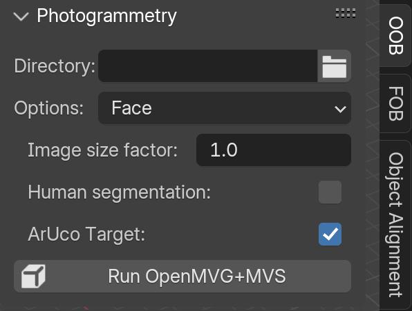
Fig. 10 The GUI.
Operation of the tool is very straightforward:
1) In “Directory”, select the folder containing the images. Important! The folder must contain only the image sequence to be converted into 3D. The system supports JPG, PNG, HEIC, and any other format readable by Python’s PIL library — a significant improvement over the previous version.
2) In “Options”, select the desired preset. The default is “Face”, which produces a lightweight file optimized for surgical planning. Other options include “Object” (for scanning items such as pottery, cars, buildings, etc.) and the new experimental “Ultra!” mode, which leverages CUDA to generate highly accurate models with fine details in considerably less time while keeping the mesh light enough for smooth editing.
3) The “Image size factor” option is useful for resizing images when they are too small (causing OpenMVG+OpenMVS difficulty in reconstruction) or excessively large (leading to unnecessarily long processing times, marginal quality gains, or system crashes). The factor multiplies pixel dimensions in both X and Y.
4) If the face was photographed in a visually cluttered environment, enabling “Human segmentation” will automatically isolate only the individual’s face.
5) By default, the system automatically searches for ArUco markers (available to download here) in the images, so the “ArUco Target” option is enabled from the start.
6) Once all settings are configured, click “Run OpenMVG+MVS” to start the digitization process.
Important
Despite the detailed step-by-step explanation, the reality is that for most OOB XP users — particularly those performing facial photogrammetry for orthognathic surgery planning — the entire process reduces to just two actions: select the folder containing the photos and click “Run OpenMVG+MVS”.
Tests and Accuracy
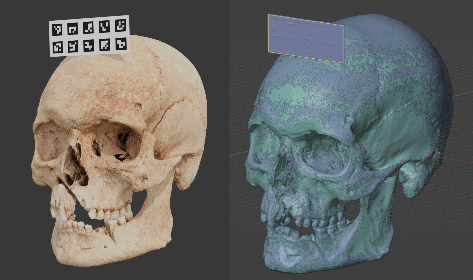
Fig. 11 On the left, the original digital model with the label composed of ArUco elements. On the right, the scene with random coloring, no visible texture, and automatic resizing and alignment.
Several tests were conducted to evaluate the accuracy of the new tool. The first two consisted of:
1) Scanning a skull with the new “Ultra!” option, manually resizing it, and comparing it with the 2022 results [Moraes_et_al_2022b_b];
2) Scanning the same skull with an ArUco marker and evaluating whether it would be compatible with the 2022 version (Fig. 11).
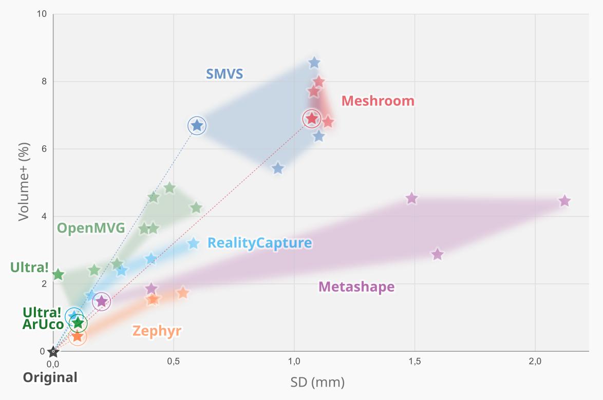
Fig. 12 Graph showing the two new scans, “Ultra!” and “Ultra! ArUco”, which can be seen highlighted in the lower left part.
Surprisingly, the new results significantly outperformed the previous version of OpenMVG+MVS, producing metrics that placed the solution on equal footing with proprietary software (Fig. 12). On one hand, the manually resized “Ultra!” version had a standard deviation close to zero, although the volume matched the best result from the previous version (indicating that in the reconstruction, few vertices generated the volumetric error). This is explained by the improvement in fine details, as will be seen later. For this first test, the 2022 image sequence was used, which did not include ArUco labels. For the test with such labels, it was necessary to generate a new sequence, as seen in figure Fig. 11, resulting in a model closer to the absolute (digital) both in terms of fine details and volumetry. The most interesting and noteworthy aspect is that this result was achieved completely automatically.
Ranking |
ID |
Factor Vol_SD |
|---|---|---|
0 |
Original |
0.00 |
1 |
4K img ultra ZPY |
0,79 |
2 |
MVG Ultra! ArUco |
1.04 |
3 |
4K img HD RC |
1.05 |
4 |
4K img ULTRA MSP |
1.30 |
5 |
4K img RC |
1.34 |
6 |
2K img ultra ZPY |
1.39 |
7 |
4K video ultra ZPY |
1.40 |
8 |
2K video ultra ZPY |
1.50 |
9 |
4K img MSP |
1.51 |
10 |
4K img MVG Ultra! |
1.51 |
The image sequence from the 2022 study consisted of files in 4K format (3840x2160 px, 8.3 megapixels) and 2K (1920x1080 px, or 2.1 megapixels), whereas the images used for the current study—that is, those employed in “MVG Ultra! ArUco” and the subsequent tests presented below—have dimensions of 2250x2750 px, or 6.19 megapixels. Thus, they are smaller than 4K but larger than 2K. This makes the result (Table 1) even more remarkable, as it was achieved fully automatically and with images smaller than those of the remaining top 4.
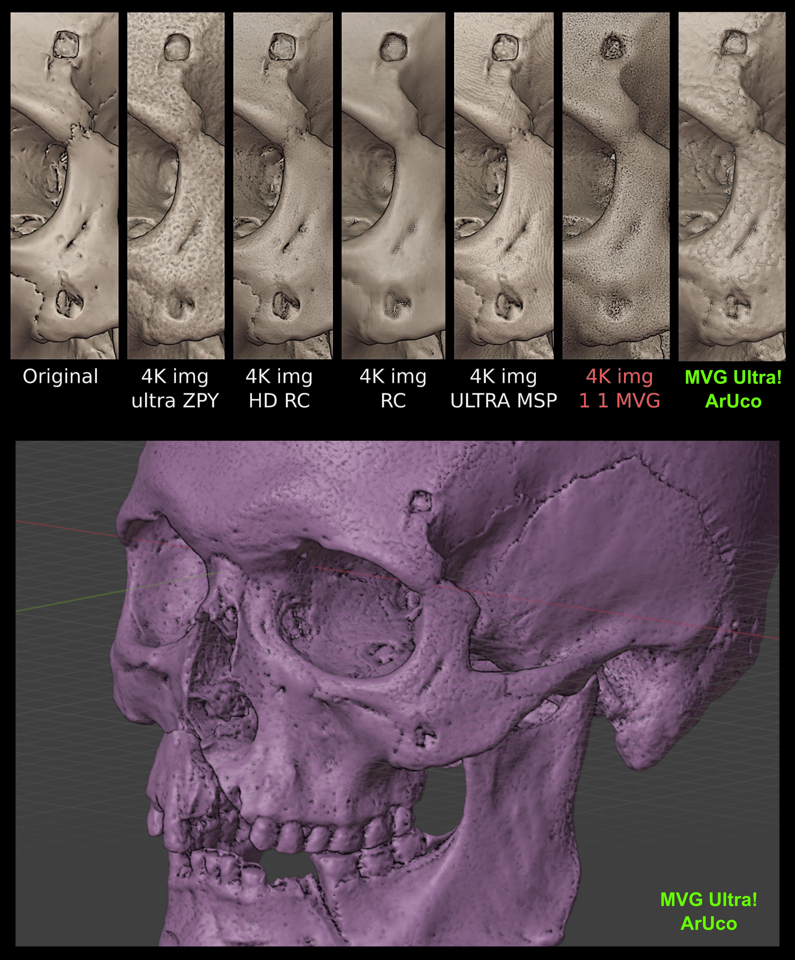
Fig. 13 Top: detailed comparison starting from the original (left) and the other scans (right). Bottom: Scanned surface from MVG Ultra! ArUco showing a significant level of detail.
Rank. |
Factor Vol_SD |
Details |
|---|---|---|
1 |
Zephyr |
Metashape |
2 |
OpenMVG+MVS |
RealityCapture |
3 |
RealityCapture |
OpenMVG+MVS |
4 |
MetaShape |
Zephyr |
With the result of the current scan, it is possible to compare it with the previous version and other photogrammetry software. In the composite image showing the models with the best resolution and alignment (Fig. 13), where the original model with absolute precision is seen in the upper left, and the current scan (MVG Ultra! ArUco) is on the far upper right, it is clear that, compared to the previous version (4K img 1 1 MVG), the quality of fine details has improved significantly—to the point of matching or even surpassing the overall first-place winner in the ranking, namely “4K img ultra ZPY” (Zephyr). Interestingly, it is also observed that although “4K ima ULTRA MSP” (Metashape) ranked fourth overall, in terms of fine detail quality it outperforms the others, being surpassed only by the third-place entry, “4K img HD RC” (RealityCapture)—thus reversing the order of the top four when the sole criterion is higher definition of details (Table 2). This entanglement only highlights that, overall, all four tools are on the same level and serve well the purpose of digitizing objects with maximum compatibility regarding real volume. The difference between this study and the one from 2022 is that this time OpenMVG+MVS not only approached the group of proprietary tools—it has joined them and delivers similar, or even better, results while being free, open-source, and cross-platform.
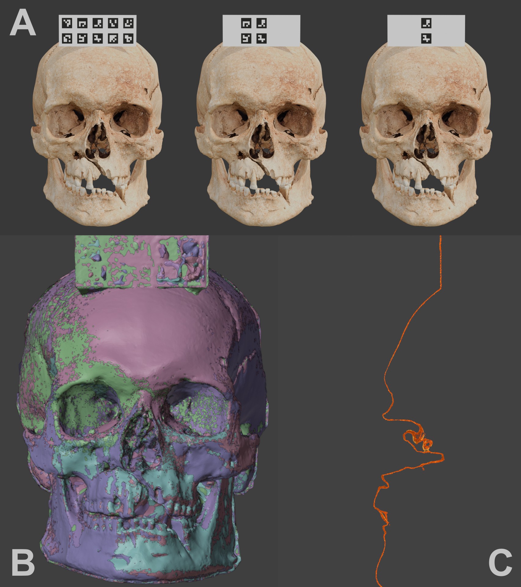
Fig. 14 A) Different captures with 10, 4, and 2 targets (all sequences ranged from 10 down to 1). B) Solid view of the aligned skulls. C) Clipping border through the central elements.
Another test was conducted to evaluate the accuracy of scaling and alignment in relation to the number of ArUco targets present. For this, 10 renderings were performed, each with 30 captures taken in an arc around the frontal part of the skull, starting with 10 small targets and progressively decreasing to just one (Fig. 13, A). Each sequence was processed to generate the model, and ArUco target detection worked correctly from 10 down to 3 targets; errors occurred with only 2 or 1 target, resulting in 3D models without proper scale and rotation correction. Thus, a total of 8 meshes remained for comparison (Fig. 14, B). When examining a central cross-section (clipping border) of the structures, no significant difference was observed between them (Fig. 14, C), demonstrating that 3 ArUco targets are already sufficient for the task.
The test involving the digital removal of ArUco markers clearly showed that there is no significant difference between using 10 and 3 small labels. But what happens if this test is applied to a set of real photographs? It is known, for example, from the 2022 study [Moraes_et_al_2022_b] that when repeating the same model 10 times, the region near the label has an error of less than 0.20 mm, while the region farthest from it concentrates 90% of the results with submillimeter precision, with the remainder below an error of 1.20 mm due to rotation error. To assess the error in the context of reducing the number of small ArUco labels, the photograph set from the aforementioned study was reused and reprocessed for the current study.
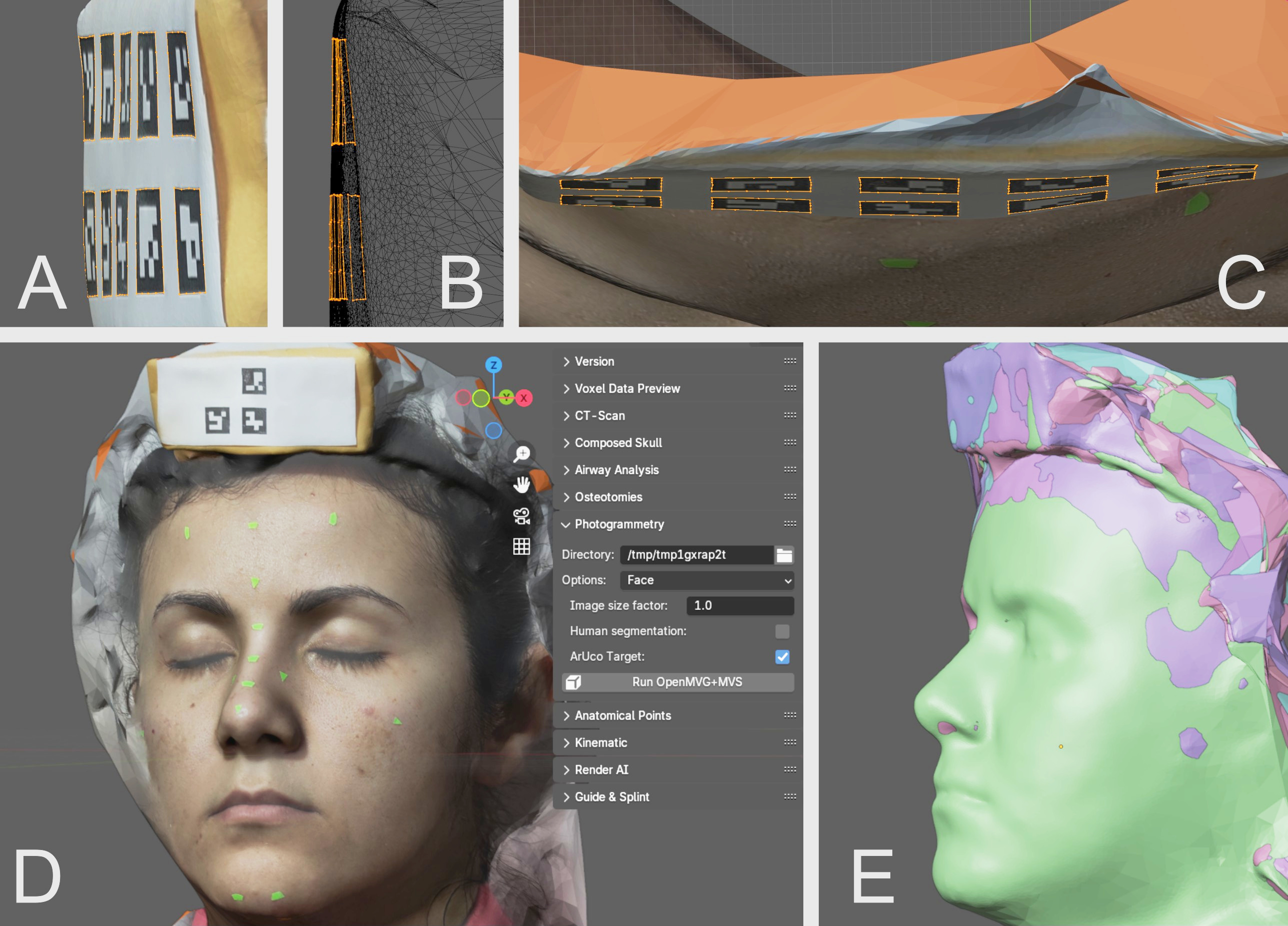
Fig. 15 A) Side view of the complete label, showing its irregularity. B) Even more lateralized view in wireframe. C) Top view, where an arch-like deformation can be observed. D) Scan of the model with 3 small ArUco targets. E) Aligned models in solid view.
A very important fact about the structure of the label used is that it consists of a simple sheet of printer paper glued onto a folded envelope paper placed over a hair clip, which gives the label a structural deformation. This can be seen when observing it from the side (Fig. 15, A), where the undulation of the shape is evident and becomes even clearer in wireframe view (Fig. 15, B). When viewed from above, it is reinforced that this deformation affects all axes, resulting in irregular normals (perpendicular lines) between one small label and another (Fig. 15, B and C). At first glance this might seem like a problem for this type of test, but in reality it is the opposite: such a situation greatly helps in evaluating the flexibility of the markers for structural correction even with variations in plane perpendicularity. The next step was to create 10 sequences of real photographs, progressively removing the independent ArUco markers one by one (Fig. 15, D). As occurred with the fully digital test, the real-photo test worked well from 10 down to 3 markers, failing to read correctly with only 2 or 1 marker. In the end, the 8 resulting models were successfully aligned using the main label (Fig. 15, E).
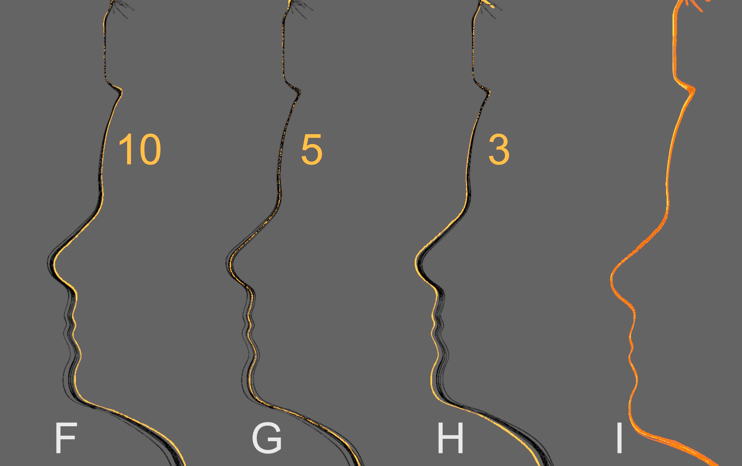
Fig. 16 F) Section view with all 8 models and the one with 10 small targets selected in orange. G) Selection of the model with 5 small targets. H) Selection of the model with only 3 targets. I) Manual rotation adjustment showing structural compatibility among all 8 models.
The result was quite revealing: the model with 10 small labels was the best aligned (Fig. 16, F), the model with 5 small labels exhibited a slight rotation (Fig. 16, G), and the model with 3 small labels showed the greatest rotation error along the X axis (Fig. 16, H). However, when manually correcting only the alignment of the models, it became clear that, in terms of scale, the results were very close, meaning the structural difference was insignificant (Fig. 16, I).
Therefore, based on both the digital and real tests, it was observed that:
A single label with 4 small markers is sufficient to generate a model with real (and reliable) scale and alignment;
Although ArUco tolerates some structural deformation, it is important to create labels that are attached to surfaces as flat as possible.
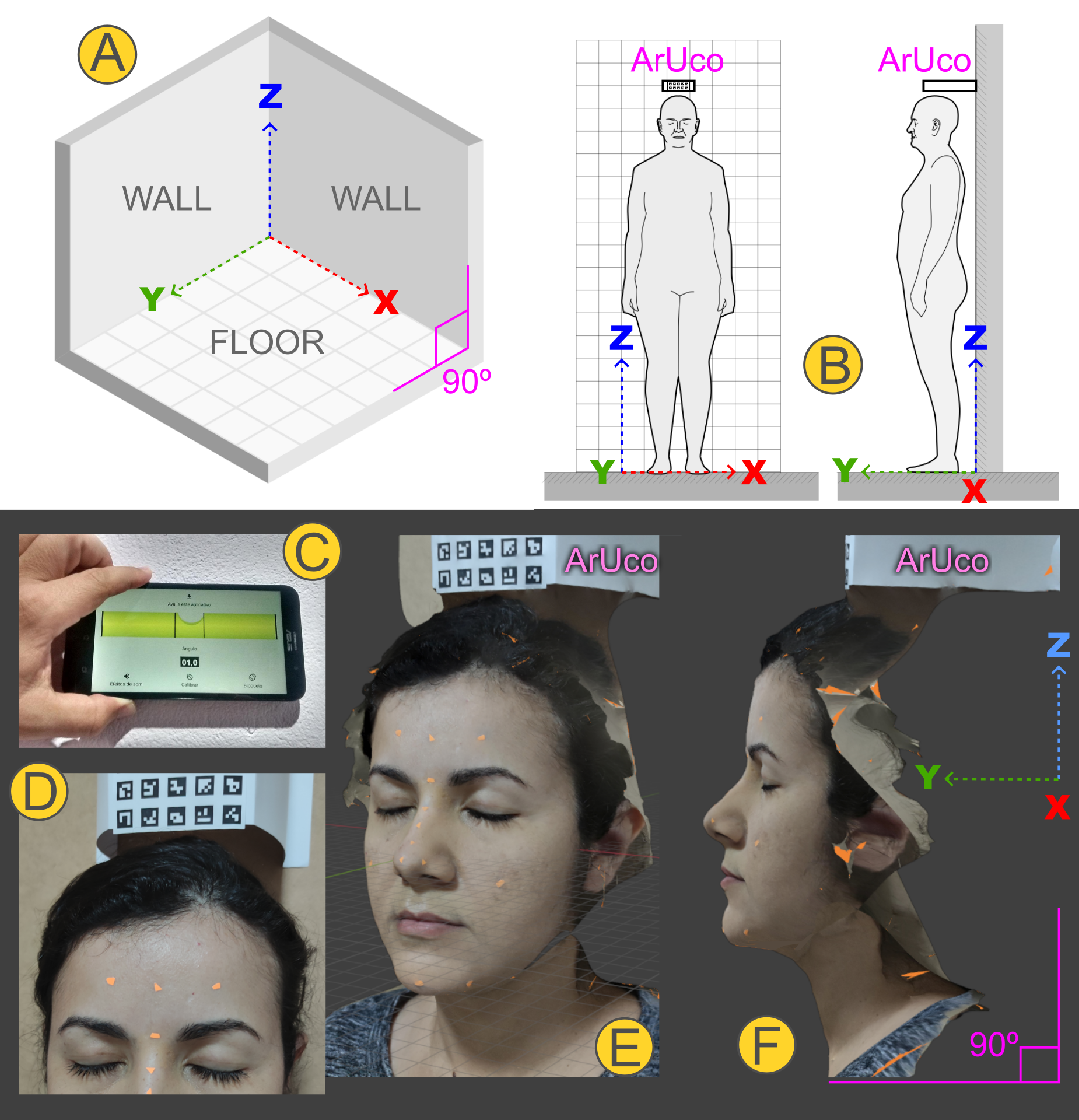
Fig. 17 A) Diagram showing the floor and walls, generally composed of right angles. B) Diagram of positioning for the photograph sequence with the natural head position; the composite ArUco label is fixed to the wall just above the head, projecting forward along the local Y axis to be captured in as many shots as possible. C and D) The photos show a real capture in which the alignment of the label fixed to the wall was adjusted using a simple free smartphone plumb and level app. E) Resulting photogrammetry mesh already scaled and aligned. F) Orthographic side detail along the positive X axis, with the natural head tilt.
Another test was carried out to meet a request frequently made by surgeons: capturing the natural head position. It was based on a protocol designed in 2016 [Moraes_et_al_2016_b], which uses the structure of walls and floor—expected to form right angles (Fig. 17, A)—by positioning the patient close to the wall with a composite ArUco label attached to it (Fig. 17, B). The specialist can create an adjustable mobile structure adapted to the patient’s height for greater practicality; however, on that occasion in 2022, the label was glued to thick cardstock that was in turn glued to the wall and aligned with the help of a plumb and level app (Fig. 17, C and D). The final image is generated reflecting the natural head position in relation to controlled angles and axes (Fig. 17, E and F).
The face capture in the example above followed the basic OrtogOnBlender protocol of 26 photos <https://www.ciceromoraes.com.br/doc/pt_br/OrtogOnBlender/Fotogrametria_Face.html>__, which can be performed in 29 seconds by a trained operator. For orthognathic surgery planning the covered region is sufficient, but some areas may be somewhat underserved (such as the nose) or not captured (such as the ears and posterior regions). For rhinoplasty planning or the creation of facial prostheses, there are broader protocols consisting of 39 or 46 photos, which remain fast and rich in detail, and options of 68 to 117 photos that require more time, attention, and processing [Moraes_et_al_2020_b].
Conclusion
The present manuscript has practically and reproducibly demonstrated that the photogrammetry tools provided by OrtogOnBlender XP enable 3D digitization that is extremely close to the real object, with submillimeter error margins. Furthermore, it delivers results comparable to those of major and widely used proprietary SfM software, despite being a completely free, open-source, and cross-platform solution. One of the traditional limitations of photogrammetry has been overcome in this version: now, with the aid of a small ArUco label, the model is automatically scaled to 1:1 and oriented according to real-world parameters, providing the user with a fully complete workflow. In addition to being free of charge, the system does not require a particularly powerful computer to run, and the photographs can be taken with mid-range smartphones.
Considering its historical development, accessibility, precision, and practical utility in helping and saving lives, this represents not merely an evolution, but a true revolution in high-quality 3D digitization for the application of computer graphics in the health sciences.
References
Bezzi, A., Bezzi, L., Moraes, C., Carrara, N., & Tiziani, M. (2013). Analisi di uno studio open source: il Taung Project. In Proceedings of ArcheoFOSS: Free, libre and open source software e open format nei processi di ricerca archeologica: VIII Edizione, Catania 2013.
Carrara, N., Bezzi, L., Bezzi, A., & Moraes, C. (2023). L’approssimazione facciale forense: Dallo studio alle mostre temporanee fino all’esibizione permamente [Abstract]. Recuperado de https://www.musei.unipd.it/sites/musei.unipd.it/files/ANMS%20abstract%20Carrara%20et%20aa.pdf
Dias, P. E. M., Moraes, C., Sousa, J. R., Beaini, T. L., & Machado, R. F. H. (2013). Escaneamento 3D por fotogrametria e software livre aplicado à Reconstrução Facial Forense. [Manuscrito não publicado]. ResearchGate. https://doi.org/10.13140/RG.2.2.30491.08489
Moraes, C., Rosa, E., & Felinto, D. (2016). O Alinhamento Natural e a Fotogrametria da Face. https://doi.org/10.13140/RG.2.2.35483.94244
Moraes, C., Sobral, D., Duarte, D. W., Cavalcanti, G. Z., Salazar-Gamarra, R., & Dornelles, R. (2020). Protocolo complementar para melhor resolução do nariz em fotogrametria 3D. figshare. https://doi.org/10.6084/M9.FIGSHARE.13010300 (Also available at: https://ortogonline.com/doc/pt_br/OrtogOnLineMag/1/Nariz.html)
Moraes, C., Kimura, R. N., Bezzi, L., & Bezzi, A. (2022). Fotogrametria com Limpeza de Pontos, Alinhamento e Redimensionamento Automáticos no OrtogOnBlender. figshare. https://doi.org/10.6084/M9.FIGSHARE.19450283
Moraes, C., Bezzi, L., Bezzi, A., Šindelář, J., Rosa, E. da, & Dornelles, R. (2022). Modelo 3D vs Fotogrametria por Imagens e Vídeo. figshare. https://doi.org/10.6084/M9.FIGSHARE.20633262
Moraes, C., Dakir, I., Startek, B., Dornelles, R., & Rosa, E. da. (2024). Segmentação de Tomografias Computadorizadas por IA no OrtogOnBlender XP. figshare. https://doi.org/10.6084/M9.FIGSHARE.27761970
Moraes, C., Startek, B., Dakir, I., Schreiner, T., Dornelles, R., & Rosa, E. da. (2025). Sistema Unificado para a Criação de um Crânio Composto no OrtogOnBlender XP. figshare. https://doi.org/10.6084/M9.FIGSHARE.28135760
Moulon, P., & Bezzi, A. (2011, June). Python Photogrammetry Toolbox: A free solution for ThreeDimensional Documentation. [Conference paper presentation]. ArcheoFoss, Naples, Italy. https://enpc.hal.science/hal-00834940v1
Moulon, P., Monasse, P., Perrot, R., & Marlet, R. (2017). OpenMVG: Open Multiple View Geometry. In Lecture Notes in Computer Science (pp. 60–74). Springer International Publishing. https://doi.org/10.1007/978-3-319-56414-2_5
Munhoz, R., Moraes, C. A. da C., Tanaka, H., & Kunkel, M. E. (2016). A digital approach for design and fabrication by rapid prototyping of orthosis for developmental dysplasia of the hip. Research on Biomedical Engineering, 32(1), 63–73. https://doi.org/10.1590/2446-4740.00316
Nascimento, B. C. G., Moraes, C. A. D. C., Neto, R. P., Rocha, B. A., Miranda, E. D. P., Bessa, J. D., Nahas, W. C., Hallak, J., Mulhall, J. P., & Gomes, C. M. (2023). (167) 3D Penile Reconstruction Imaging in Complex Peyronie’s Disease (PD): Proof of Concept Study. In The Journal of Sexual Medicine (Vol. 20, Issue Supplement_1). Oxford University Press (OUP). https://doi.org/10.1093/jsxmed/qdad060.162
Rabello, R., Rabello, M., Fecchio R., S., Moraes, C., P.E.M., D., Palma, B., & Davanco, R. R. (2016). Utilização de Tecnologia 3D Para Reconstituição Protética de Caparaça de Jabuti (Chelonoidis carbonaria) - Relato de Caso. Unpublished. https://doi.org/10.13140/RG.2.2.34596.80001
Salazar-Gamarra, R., Cárdenas-Bocanegra, A., Masch, U., Da Costa Moraes, C. A., Seelaus, R., Lopes Da Silva, J. V., & Lauria Dib, L. (2022). Color translation from monoscopic photogrammetry +ID Methodology into a Polyjet final 3D printed facial prosthesis. F1000Research, 11, 582. https://doi.org/10.12688/f1000research.111196.1
Sobral, D. S., Duarte, D. W., Dornelles, R. F. V., & Moraes, C. A. C. (2021). 3D Virtual Planning for Rhinoplasty Using a Free Add-On for Open-Source Software. Aesthetic Surgery Journal, 41(8), NP1024–NP1032. https://doi.org/10.1093/asj/sjab085